Blog Archive

Wednesday, May 25, 2016

Week 9 Update

Goals completed:

  • Adjusted code to test with shorter day lengths.
  • Positioned wires to make window more openable

Our window is now finished and ready for presentation!

The last major thing to do for the code was to make it work on a shorter cycle for demonstration purposes. We could user one of our testing program that just cycles the colors on a loop, but we wanted to demonstrate our full algorithm, including the code for dealing with the time.

The problem with our current code is that it measures time in minutes, so the shortest a day can last and still cycle through each color is 15 minutes. Our presentation time is about half that. The solution is to alter the code so that it can keep track of time in seconds, instead of minutes. We switched the data type used to store the time (int to long, for the extra storage space needed to store up to 86,400 seconds), multiplied a lot of values by 60, and got the window to work so it can change time as quickly as we need it. Now we can run through the full course of a day, scaled to the duration of our presentation.


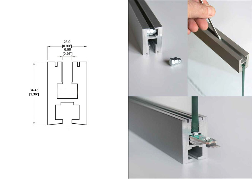
The last change to our hardware was to make the window easier to open. We were not able to remove all of the electronics from the back pane because we had no place inside the main frame to mount them. However, we were able to some of the wires and positioned the others so that they are easily unplugged. The window still has to be unplugged to be opened, but the process is much easier and less likely to accidentally pull out any wires.


The repositioned wires inside the window.


Next steps:
  • Write presentation.
  • Polish final report.

Friday, May 20, 2016

Week 8 Update

Goals completed:

  • Assembled window, including electronics
  • Finished main version of light control algorithm
  • Tested LEDs and sub-algorithms

This week we finally put together a working prototype of our window! It is not entirely complete, but it is at the stage where we can simply plug in the power cord and let it run on its own. Everything else is just minor polishing.

On the frame side, we finished the main assembly. We caulked the gaps in the corners that were caused by warping of the wood, as discussed in week 7. We mounted the back panel using a set of hinges screwed into the frame in order to allow access to the internals of the window. We also added a Velcro closure to the panel to allow it to be closed securely.

The back panel of the window, with hinges.

For the lighting, we attached the reflective sheet to the inside of the back panel using double-sided tape. We also mounted the LEDs on the inside edge of the frame, as planned. The distribution of light from this setup is still working has well as we had hoped based on last week's testing.
Inside view of the window.
Closer view of the LEDs.

We also began mounting the Arduino to the inside of the frame and constructed a port through which we connect the power cord. The Arduino mount works for testing purposes, but we still need to make a few adjustments in order to make it completely secure and to the wires remain well connected. In particular, the circuit board and the breadboard are mounted on the back panel, and the wires are not long enough to reach when the window is open all the way. We will try to either reposition the Arduino or extend the wires.

The Arduino circuit board (not mounted) and breadboard with their connecting wires detached.


On the software side, the algorithm for controlling the LEDs has been completely written, although not thoroughly tested. The way the code works, the LEDs change color over the course of hours or, at a minimum, many minutes. We did, however write a few testing programs for various parts of the algorithm and, in particular, the LEDs (as shown below).


Our window cycling through its different colors.

It is easier to test the LEDs with a program that simply cycles through each different color we use, as the above code does, than one that checks the current time. However, for presentation purposes, we would like to demonstrate our actual algorithm. We will need to adjust the code to allow it to set a day length of only a few minutes without disrupting the normal functionality.

The colors of the LED are also not set in stone. There are a few factors that make the current colors less than ideal: first, the color intensity to RGB algorithm we use is designed for photography color correction and may not match perfectly what the human eye sees in sunlight; second, color and intensity values for our light are from a nursing home schedule, which increases the brightness of light to accommodate elderly residents with poor eyesight. They are currently our best sources of data, but we will continue to search for other data or make adjustments to make the light more comfortable for our own eyes to look at.


Next steps:

  • Ensure electronics are mounted securely
  • Adjust code to allow demonstration of the algorithm
  • Adjust lighting color and intensity as needed

Saturday, May 7, 2016

Week 7 Update

Goals completed:

  • Assembled main window frame
  • Finalized method of LED lighting

This week we completed the main assembly of the window frame. We screwed the four siding pieces together at the corners after fitting the diffusing plate securely inside its housing.

Front View of Window Assembly
A problem that we ran into while screwing the wooden pieces together was that there was a gap that would form in between the pieces even with a clamp holding them together. This formation of a gap was due to the wooden 2x4s being warped, twisted, and not perfectly square. To fix this, we intend to add caulk in between the gaps and edges to seal the inside and assure that no light escapes without going through the light diffusing panel.
The corners of our window need to be caulked.

In terms of lighting, this week we solved our last difficulties with the choice between side lighting and backlighting. Dr. Ellis provided us with a sheet of highly reflective material which will be affixed to the backboard of the window. In this setup, with the LEDs mounted to the inside siding of the frame, the lights project along the inside of the window and are diffused outward. Any loss of intensity from the sideways angle is made up for by the light reflected by the back sheet. This method proves very effective at lighting the window both brightly and evenly.

The reflective sheet. 

On the software side, there is not much to discuss. We have already addressed the main design challenges (interfacing with the LEDs and the RTC) and are just in the stage of finishing up small pieces and debugging the code.

Next steps:
  • Finish main frame
  • Mount back panel and electronics
  • Keep coding

Thursday, May 5, 2016

Week 6 Update

Goals Completed:

  • Received RTC and began work on time code
  • Began working on window assembly
  • Completed work on


For software, we received out real-time clock this week, which means we have everything we need for our electronics. We are in the process of finishing up the Arduino script and adding in the time library components. We have the most of the code to determine the light output for each time; we just need a way to match up our schedule with what the time currently is.
Our main steps in figuring out this part is to simply read up on the various time libraries available and start wiring together the physical RTC unit. Other than that, we just need to keep coding.

Our window prototype, almost ready to be assembled.
Last week in lab, we cut the side pieces of the window too large, forgetting to account for the inset of the ULED panel. This was an easy fix, however: we simply cut a 1/2" parallel to one side of each side piece. We also cut the incision for the panel to slide into, a 1/4" deep cut located 1/4" from the front of the wooden frame piece. Now that all of the cuts have been made, we were ready to assemble the four pieces together, and also, insert the panel.

Next Steps:

  • Begin assembly of window.
  • Finish Arduino script.
  • Begin design proposal draft.

Thursday, April 28, 2016

Week 5 Update

Goals Completed:

  • Created code for time and color conversion
  • Cut wood
  • Figured out Arduino voltage output with PWM

We made a lot of progress on the software this week. We are almost done with the coding on the assignments of the times and color temperatures from the daylight matching research we have found (the code isn't difficult, just long and bulky). We also found a way to convert color temperatures, which is the data we have found on LED daylight matching, into RGB values, which is we need to give to the LEDs. We took this code, designed for color-correcting photos based on lighting conditions, and modified it to run on an Arduino.

Our current algorithm is as follows:

Setup:
Assign wakeup and bedtimes.
Divide the number of waking hours by 15; this is our time interval.
Divide the day into time intervals.
Assign each time interval a color temperature.

Continuous loop:
Check the time.
Get appropriate color temperature.
Convert color temperature to RGB.
Send voltage information to LEDs.
Repeat.

The remaining code deals with the clock and voltage functions.

This week we got ourselves familiar with the hardware behind changing the LED RGB values. It is done with pulse width modulation (PWM). Voltage from the Arduino can only be at 0 or 5V, but by adjusting the frequency at which the voltage is applied, it can act like a fraction of a voltage.

Changing the duty cycle changes the voltage output.


 Our breadboarded PWM circuit.
Upon testing the LEDs with some sample color changing code, we found that the lights would flicker at certain PWM values. We did some research and found that it can happen at low PWM values when the PWM is a certain mode, so we increased the values and fixed that problem. Now, the circuit is stable and we can continue with color testing.

When testing the LEDs with the diffusing sheet, we discovered that edge lighting does not work as we planned. It leaks around the edges much more than we anticipated and, more importantly, does not actually illuminate the entire sheet. Once we looked further into the properties of the material used in the panel (the same as used in these TVs, it turned out that the material is usually backlit. Testing the window with the LEDs behind it proved much more successful. Our new plan is to backlight the window with several strips of LEDs about an inch back from the pane, to allow the light to spread out and not appear as single dots.

Now that we are not edgelighting the window, we can ignore the problem of trying to fit the LEDs in to the sides of the frame. The frame will now hold the pane in simple slits along the edges and have space on the back panel to hold the LEDs in place. We made some more cuts on the wood this week, including the angle cuts to put the 2-by-4s together at the corners, but errors were made and we will have to correct this in lab next week before we can assemble the frame.

Next Steps:
  • Program clock and voltage code.
  • Fix frame cuts.
  • Assemble frame.
  • Start installing lights into frame.

Thursday, April 21, 2016

Week 4 Update

Goals completed:

  • Ordered most of the materials
  • Started building frame
  • Started planning 3D-printed frame materials
  • Downloaded all necessary software for Arduino
  • Wrote Arduino pseudocode
  • Began wiring lights

This week we really started getting into the meat of our design. We now have most of the materials we need to do the work, and most of the planning is done.

On the frame side of the project, we got all the lumber and a diffusing plate (thank you Dr. Ellis and Mr. Zuker), and we have a plan for what it should look like. Now that we have the diffusing plate and the LEDs, we can figure out how we're going to get them lit. Our current plan is to use sidelighting, aligning the lights with the side of the diffusing plate instead of the back to spread the light throughout the window pane. Some research shows that we probably want a frame for the LED strips that looks something like this.
A slot designed for LED sidelighting.


Our best idea is to see if we can 3D-print several strips of this to go along the sides of the plate, but it could take up more material than we have available.

It looks like we will need to carve channels in the wood in order to fit the LED holder. We also considered trying to carve a holder directly into the wood, but we don't think we can do that much detail. We did make our first cuts, so now we have the wood cut down to the correct sizes. We still need to make the detail cuts and diagonal cuts before we begin fitting the pieces together.

On the electronics side of things, we finally got our Arduino and LEDs delivered and could begin wiring them together. We learned how to wire the LEDs to the breadboard correctly and tested it with a sample color-changing program from the LED seller, modified slightly. It worked great, as shown in the video below. We also tested out soldering the wires in place. The initial test seems promising, but some wires came loose. We need to work out a way to make sure everything stays in place.
Our modified version of the color-changing code.

Our LEDs changing color with sample code.


On the software side, we developed a plan for how to change the lights to match daylight. An early version of the pseudocode is shown below. Essentially, we give the code a wakeup time and a bedtime and divide it into small segments. Every time the time enters a new segment, the voltages for the RBG values of the LEDs are adjusted to make the correct color.
A brief pseudocode for the program.


The data we're using as  a guideline for what color the lights should be comes from this experiment of daylight matching in nursing homes. We will take their schedule, scale it based on our wakeup and bedtime, and map the LED colors accordingly. The bulk of the programming left is just making the if/elses and setting each lighting condition, in addition to converting color temperatures into RGB values.
The basis for our lighting schedule.

Next Steps:

  • Finalize lighting scheme
  • Continue coding
  • 3D-print LED holder
  • Build frame
  • Continue wiring the lights

Friday, April 15, 2016

Week 3 Update

Goals completed:
  • Determine what resources are available from people
  • Begin more in-depth research
  • Begin planning Arduino pseudocode and wiring
  • Begin designing frame
This week was largely our time for research. We dug deeper into the literature and and have a much better idea of the underlying principles of LED daylight matching. We also got some good data on exactly how our LEDs should change color; we're still looking for good data on how the spectrum changes during the day, hour by hour. Some of the information we found regarding daylight matching are shown in the images below.
Different times of day and weather conditions produce different types of daylight.
en.wikipedia.org
Data from one of Dr. Ellis's articles on LED daylight matching
http://www.bauarchitecture.com/research.daylightleds.shtml

The emission spectrum of LEDs closely models that of daylight.
http://www.bauarchitecture.com/research.daylightleds.shtml
On the software side of the design, we have begun delving into Arduino code design. The basic idea is that we will have the program check the time of day and see what RGB values it should assign to the light based on that time (we have yet to determine that part). Then it should feed the proper voltage to each wire of the LED to make it the correct color.

One important thing we figured out is how to keep the window running in on time and making sure it can be unplugged. We determined that once we load the program onto the Arduino, it will run automatically whenever it is plugged in, even if it gets unplugged at some point. If we get a Real Time Clock system, the RTC will keep track of the time, even if the Arduino gets unplugged, as long as it stays battery powered.

We also learned the basics of how we need to wire the Arduino. The Arduino itself needs a power source, as do the LEDs, since the Arduino doesn't have enough voltage to run the entire light. However, the Arduino will connect to the parts of the LEDs that determine RGB values, which can be changed by varying voltage with a pulse width modulator. The RTC is designed to interface specifically with the Arduino, so that is no difficulty.

On the hardware side, we developed a basic plan for the frame. It will be constructed out of two-by-fours with slits that a diffusing plate can be slid into. This will leave a hollow space behind the window, which will allow the LEDs to placed on the back of the window pane and have a spot to place the Arduino and any other electronics. This space will be covered by a sheet of wood to make everything into a self-contained package.

We also looked further into materials purchase. We aren't quite ready to order anything until we figure out how things will interface, in particular the LEDs and the Arduino. Luckily, we managed to get an Arduino lent to us from the Engineering department, so we can begin programming with it as soon as we pick it up from lab. Then we can figure out how it connects to LEDs and order them.
We also sent an e-mail to Dr. Ellis's contact at Walalight to ask his advice on materials for the diffusing plate for the window.

Next Steps:
  • Order materials
  • Start programming with the Arduino
  • Begin construction of window frame
  • Find more concrete details on controlling the LEDs