- Determine what resources are available from people
- Begin more in-depth research
- Begin planning Arduino pseudocode and wiring
- Begin designing frame
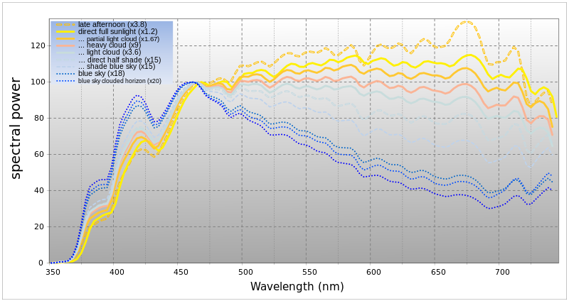 |
| Different times of day and weather conditions produce different types of daylight. en.wikipedia.org |
 |
| Data from one of Dr. Ellis's articles on LED daylight matching http://www.bauarchitecture.com/research.daylightleds.shtml |
 |
| The emission spectrum of LEDs closely models that of daylight. http://www.bauarchitecture.com/research.daylightleds.shtml |
One important thing we figured out is how to keep the window running in on time and making sure it can be unplugged. We determined that once we load the program onto the Arduino, it will run automatically whenever it is plugged in, even if it gets unplugged at some point. If we get a Real Time Clock system, the RTC will keep track of the time, even if the Arduino gets unplugged, as long as it stays battery powered.
We also learned the basics of how we need to wire the Arduino. The Arduino itself needs a power source, as do the LEDs, since the Arduino doesn't have enough voltage to run the entire light. However, the Arduino will connect to the parts of the LEDs that determine RGB values, which can be changed by varying voltage with a pulse width modulator. The RTC is designed to interface specifically with the Arduino, so that is no difficulty.
On the hardware side, we developed a basic plan for the frame. It will be constructed out of two-by-fours with slits that a diffusing plate can be slid into. This will leave a hollow space behind the window, which will allow the LEDs to placed on the back of the window pane and have a spot to place the Arduino and any other electronics. This space will be covered by a sheet of wood to make everything into a self-contained package.
We also looked further into materials purchase. We aren't quite ready to order anything until we figure out how things will interface, in particular the LEDs and the Arduino. Luckily, we managed to get an Arduino lent to us from the Engineering department, so we can begin programming with it as soon as we pick it up from lab. Then we can figure out how it connects to LEDs and order them.
We also sent an e-mail to Dr. Ellis's contact at Walalight to ask his advice on materials for the diffusing plate for the window.
Next Steps:
- Order materials
- Start programming with the Arduino
- Begin construction of window frame
- Find more concrete details on controlling the LEDs
No comments:
Post a Comment